
Linear tracks and positioners
A robot reaches one radius. A linear track — the 7th axis — extends it along the part or across several stations; a positioner turns the part to the robot instead of asking the robot to reach around it. Both belong in the quotation with the robot, not after it: mounting height, cable carrier and Ex rating are decisions that change the robot selection.
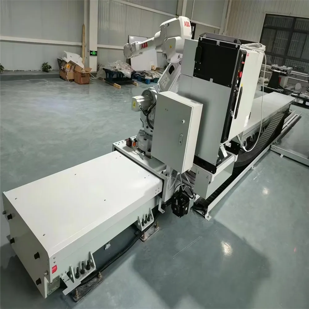
Linear tracks — three standard constructions
| Construction | Total width | Guideway surface | Mounting height | Load | Section lengths |
|---|---|---|---|---|---|
| Standard track (mass produced) | 740 mm | 500 mm | 360 mm ±20 | 500 kg rated | 3, 4, 5, 6 m — spliceable |
| Cast-iron ground track II | 1340 mm | 1000 mm | 450–490 mm | robots of 1,000–5,000 kg total weight | 3 m, 4 m; any whole metre above 3 m (except 5 m) |
| Cast-iron ground track III | 1440 mm | 1100 mm | 529 mm ±15 | robots of 3,000–10,000 kg total weight | 3 m, 4 m; any whole metre above 3 m (except 5 m) |
Manufacturer datasheet values. Standard track rated speed 600 mm/s. A single section can be made up to 8 m; longer axes are spliced. Where the mounting height is fixed by the booth or the conveyor, the robot base is raised or the whole track is elevated to suit.
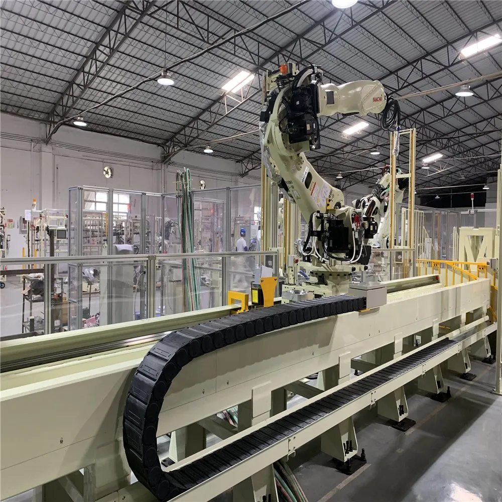
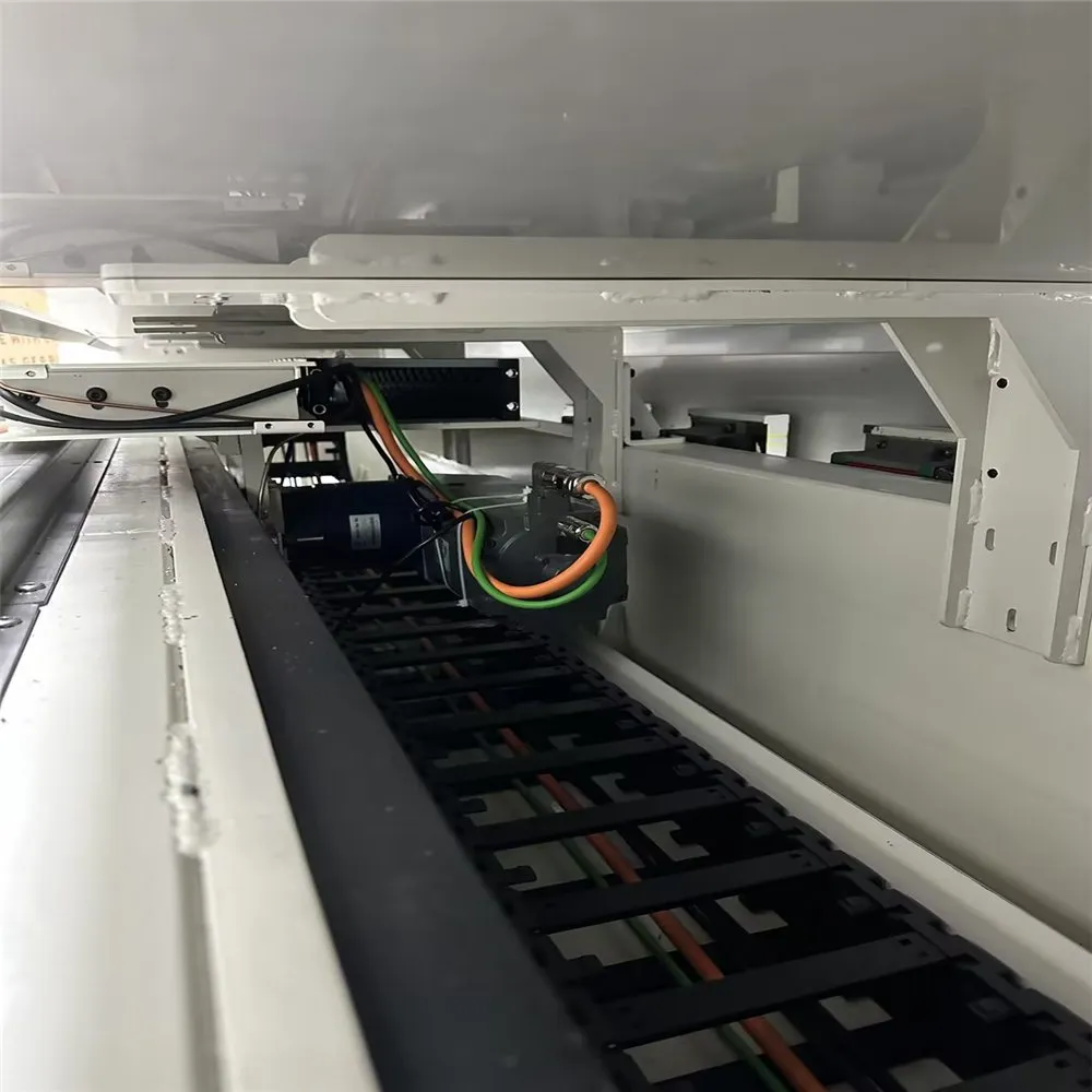
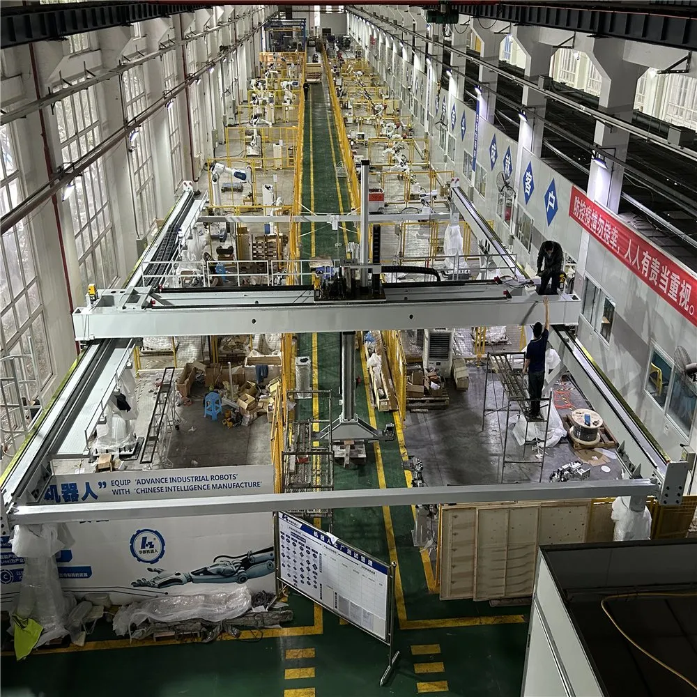
What is inside the track
Load-bearing
- Frame in welded, cast or rail construction, chosen for the load and the stiffness required.
- Carriage assembly: robot base, connecting plate, slide-block plate, motor plate.
- Linear guides and blocks: HIWIN as standard; PMI, THK or domestic on request.
- Levelling feet with ±40 mm adjustment.
Drive
- Servo motor — usually the robot brand's own; we assist with the selection.
- Planetary helical gearbox: Shimpo as standard; Tamagawa, Motovario or domestic on request.
- Rack and pinion: YYC, APEX, LEAN or BORCH.
Protection
- Guideway covers: sheet-metal, chequered plate or bellows — paint, weld spatter and dust each want a different cover.
- Travel limits: proximity switches plus mechanical stops.
- Lubrication: pump, distributor, lines, nipples and felt pinion lubricator.
- Cable carrier assembly: chain, brackets, trough and support rollers.
Inside a paint booth
Ex-rated motors and Ex-rated cable carriers, plus covers and lubrication that survive solvent and booth cleaning. On a bus-body line proposal this meant six 15 m tracks with Ex motors and Ex cable carriers — a different bill of materials from a welding-cell track of the same length, and one of the reasons that line's value sat in the booths and ovens rather than in the robots.
Positioners — single axis
| Model | Type | Payload | Spindle centre height | Speed | Rotation |
|---|---|---|---|---|---|
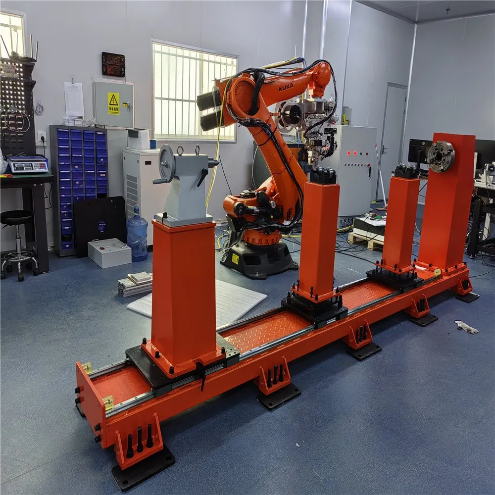
| ZB-D1-500 | Single-axis headstock–tailstock frame | 500 kg | 650 mm | 60 °/s | ±180° |
| ZB-D1-1000 | Single-axis headstock–tailstock frame | 1000 kg | 650 mm | 50 °/s | ±180° |
| ZB-D2-500 | Headstock–tailstock beam type | 500 kg | 650 mm | 60 °/s | ±180° |
| ZB-D2-1000 | Headstock–tailstock beam type | 1000 kg | 650 mm | 50 °/s | ±180° |
| ZB-D3-500 | Horizontal rotary table, Ø600 mm | 500 kg | — | 60 °/s | ±360° |
| ZB-D3-1000 | Horizontal rotary table, Ø800 mm | 1000 kg | — | 50 °/s | ±360° |
| ZB-D4-500 | L-type | 500 kg | 650 mm | 70 °/s | ±180° |
| ZB-D4-1000 | L-type | 1000 kg | 800 mm | 60 °/s | ±180° |
Repeatability 0.05 mm per manufacturer datasheet. Parameters are customisable to the workpiece.
Positioners — two axis
| Model | Type | Payload | Rotation radius | Speed | Rotation |
|---|---|---|---|---|---|
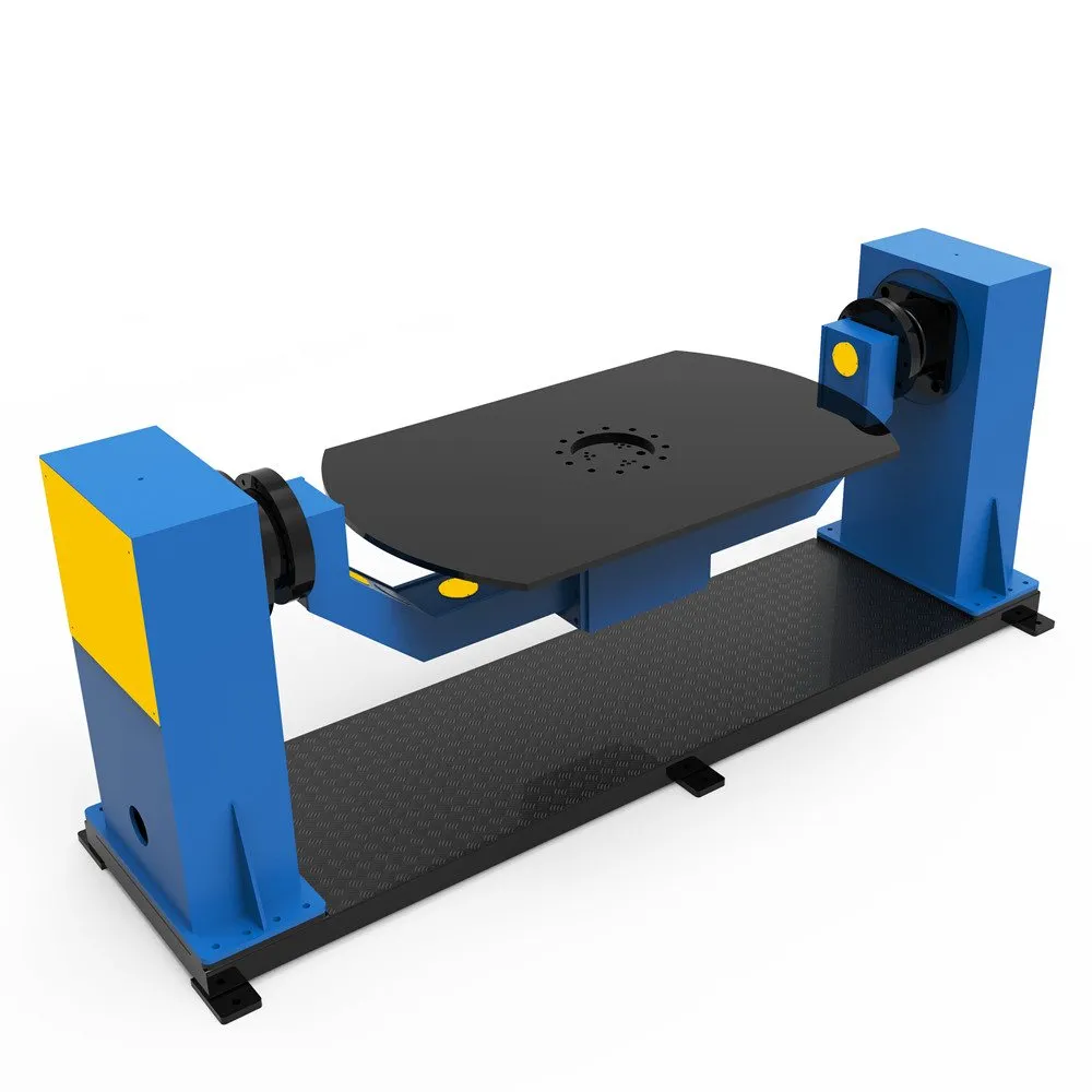
| ZB-S1-300 | Two-axis, general | 300 kg | 500 mm | axis 1: 60 °/s · axis 2: 80 °/s | axis 1 ±90° · axis 2 ±360° |
| ZB-S1-500 | Two-axis, general | 500 kg | 600 mm | axis 1: 50 °/s · axis 2: 50 °/s | axis 1 ±90° · axis 2 ±360° |
| ZB-SL2-500 | Two-axis, L type | 500 kg | 400 mm | axis 1: 50 °/s · axis 2: 70 °/s | axis 1 ±175° · axis 2 ±360° |
| ZB-SL2-1000 | Two-axis, L type | 1000 kg | 500 mm | axis 1: 50 °/s · axis 2: 70 °/s | axis 1 ±180° · axis 2 ±360° |
| ZB-SL2-2000 | Two-axis, L type | 2000 kg | 600 mm | axis 1: 20 °/s · axis 2: 20 °/s | axis 1 ±180° · axis 2 ±360° |
| ZB-SC3-500 | Two-axis, C type | 500 kg | 450 mm | axis 1: 60 °/s · axis 2: 75 °/s | axis 1 ±175° · axis 2 ±360° |
| ZB-SC3-1000 | Two-axis, C type | 1000 kg | 650 mm | axis 1: 20 °/s · axis 2: 75 °/s | axis 1 ±175° · axis 2 ±360° |
| ZB-SHX4-500 | Two-axis, horizontal rotating frame | 500 kg | 400 mm | axis 1: 50 °/s · axis 2: 70 °/s | axis 1 ±175° · axis 2 ±360° |
| ZB-SHX4-1000 | Two-axis, horizontal rotating frame | 1000 kg | 500 mm | axis 1: 50 °/s · axis 2: 70 °/s | axis 1 ±175° · axis 2 ±360° |
| ZB-SHX4-2000 | Two-axis, horizontal rotating frame | 2000 kg | 600 mm | axis 1: 17 °/s · axis 2: 17 °/s | axis 1 ±175° · axis 2 ±360° |
Repeatability 0.1–0.15 mm per manufacturer datasheet. Three-axis systems are available; ask for the configuration that fits your part.
Delivered with the robot, packed for the route
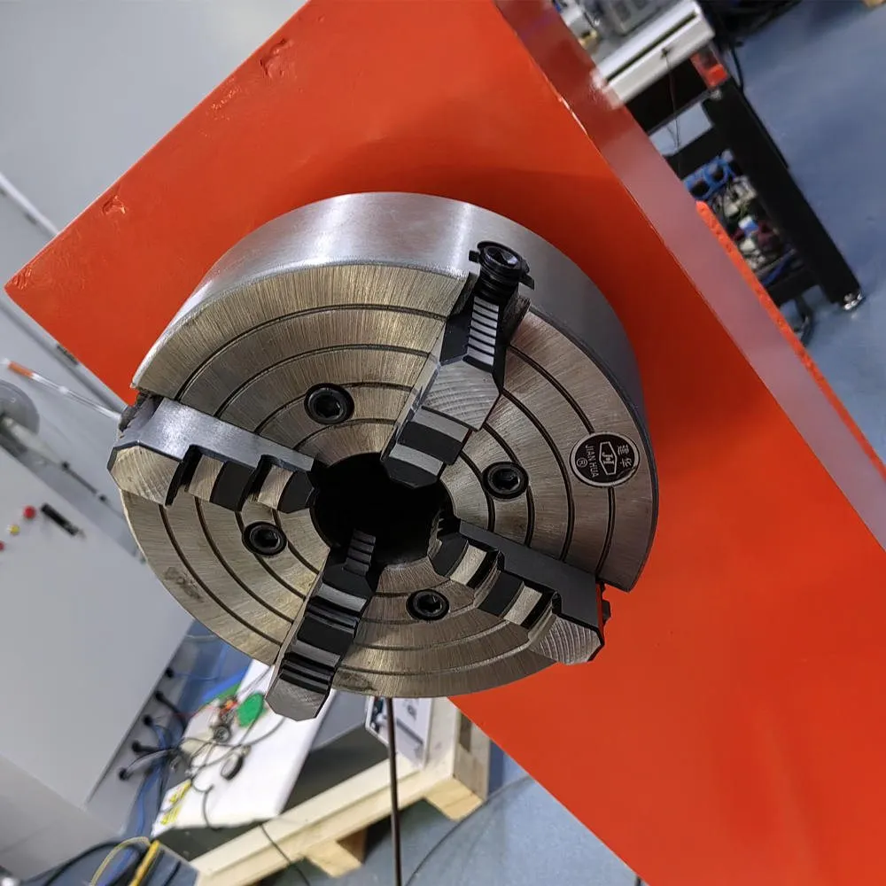
Tracks and positioners are supplied together with the robot as one scope: mechanical interface, drive package, cable routing, safety devices and the acceptance test that proves the axis moves the robot the way the layout assumed. On a delivered hardware package for a Russian integrator this was a KUKA KR20 R1810-2 with a KRC4 cabinet, a three-external-axis drive package and a self-centering single-axis vertical positioner with a Ø1400 mm faceplate, plus motors and cables for a second positioner.
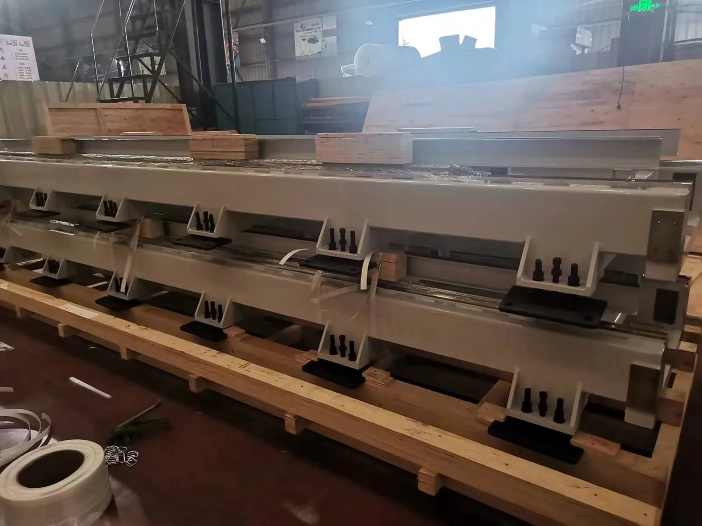
Long tracks ship in sections and are spliced on site; crating and container loading are planned around the section length, because a 15 m axis is a packing decision before it is a price.
Frequently asked questions
How long can a linear track be?
Sections are spliced: the standard track comes in 3, 4, 5 and 6 m sections and the cast-iron tracks in whole metres from 3 m (5 m excepted), with a single section up to 8 m. We have engineered a 72 m floor track for a painting layout and 15 m explosion-proof tracks for a bus-body line. Length is quoted per metre — the same unit you will check it in.
Can one track carry more than one robot?
Yes. A track can carry one or several robots, and one robot on a track can serve several stations. Which arrangement is cheaper follows from the cycle time, not from the track price.
What changes for an explosion-proof paint booth?
Inside the booth the axis needs Ex-rated motors and Ex-rated cable carriers, and a cover and lubrication arrangement that survives solvent and cleaning. That is a different bill of materials from a welding-cell track of the same length, and it is quoted as such.
Do you supply the servo motors?
Usually the robot brand dictates the motor and many customers buy the motors with the robot; we assist with the selection and build the track to match. Where we supply the complete axis, the motor and gearbox are named in the offer.
Which positioner do I need for my part?
Send the part weight, the envelope and the centre of gravity relative to the faceplate, plus the weld or coating positions. Payload alone does not select a positioner — an off-centre load at 600 mm radius is a different machine from the same mass on the faceplate.
Request a quote Send the part weight, the envelope and the required travel — we return a track length and a positioner model.